English
An induction loop refers to the cabling on the roof that can cause overvoltage in the solar power system due to nearby lightning strikes. By minimizing the size of the induction loop, this risk is reduced.
For most people, the physics lessons from high school are long forgotten. Who still remembers the corkscrew rule for electromagnetism? Or the effects of magnetic flux through a coil? And why did we ever need to learn all that?
What’s important to remember is that a changing magnetic flux flowing through a coil induces a current in the coil. This is the principle of a dynamo: between two magnets, there’s a coil that rotates, causing the magnetic flux through the coil to change continuously, generating a current that, for example, powers a bicycle light.
The larger the coil's surface area, the greater the current induced (or: generated). The relationship is described by Faraday’s Law (remember?)
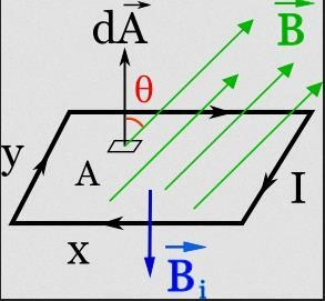
Faraday’s Law is relevant to us when it comes to lightning. During a lightning strike, a strong magnetic field is briefly created around the lightning bolt. All electrical circuits near the strike experience a magnetic flux flowing through them. In the image below, the magnetic flux is shown by the green arrows and the letter B. This induces a current (I) in those circuits.
The larger the circuit's surface area, the greater the induced current. The cables connecting solar panels on a roof also form a circuit. When we talk about reducing the induction loop, we mean arranging the cables in such a way that the area within the circuit is as small as possible. This way, we reduce the chance of a large current spike due to nearby lightning strikes.
More Cable, Fewer Problems
In order to reduce the area within the induction loop as much as possible, cables should be mounted close together. This can result in the use of more DC cable than you would think necessary, as shown in the image below:
In the right image, the DC cable from the panel at the bottom right runs back towards the inverter, taking the shortest route. This creates a large surface area within the DC cabling. In the left image, the returning DC cable is laid back alongside the outgoing cable. This keeps the surface area within the cables as small as possible, significantly reducing the chance of a current spike from lightning strikes in the vicinity of the PV system.

Proper Installation?
Keeping the induction loop as small as possible is something that the installers at Zonnefabriek are trained for and always keep in mind. If this is not done correctly in an installation, there’s a higher chance of damage to the panels and inverter when lightning strikes in the area. However, it’s very difficult to determine afterward whether damage could have been avoided if your installers had accounted for the induction loop. It comes down to a mix of chance (how close was the strike to the PV system, how much energy was in the lighnting strike?), and good preparation (did the installers lay the cables close together?)
A small induction loop is a precaution that should come as standard with a careful installation, carried out according to the correct installation methods. This shows whether an installer has sufficient knowledge of solar panel systems, even if they can't immediately recall Faraday's Law.